NUKRAX
A self-contained RF intelligence platform. Scan WiFi, BLE and the full 2.4 GHz spectrum. Broadcast alerts to nearby devices. Run JR.IO — a dual-radio 2.4 GHz disruptor at maximum power.
Both NRF24L01+PA/LNA modules output a continuous unmodulated 2.4 GHz carrier at maximum power. Slide switch selects mode live. Zero-delay tight loop for maximum efficiency.
Scans all nearby networks including hidden SSIDs. Shows SSID, channel, RSSI, BSSID and encryption status. Sorted by signal strength.
802.11 B/G/N6-second passive BLE advertisement scan. Displays device name, MAC address and RSSI. Identifies unnamed advertisement-only devices.
BLE 4.x / 5.xBoth NRF24 radios sweep simultaneously. Full 126-channel band visualised as a bar graph on the OLED. WiFi channels 1, 6, 11 marked.
126 ChannelsBroadcasts custom messages to all nearby devices with no connection required. WiFi SSID blast, BLE beacon, or both simultaneously at max TX power.
No Connection Needed| Component | Details | Notes | Qty |
|---|---|---|---|
| ESP32-WROOM-32 | Dual-core 240 MHz, WiFi + BLE built-in | Any standard 38-pin dev board | × 2 |
| NRF24L01+PA/LNA | +20 dBm TX, external antenna | Must be PA/LNA version | × 2 |
| 0.96" OLED SSD1306 | 128×64 I2C 4-pin, SDA=GPIO4 SCL=GPIO5 | Blue or white, both work | × 1 |
| Push Button 6×6mm | UP · DOWN · MIDDLE tactile | Active-LOW with pull-up | × 3 |
| Slide Switch 3-pin | JR.IO mode select, GPIO33 on ESP1 | middle=GND · right=GPIO33 | × 1 |
| 100µF Capacitor | Electrolytic, VCC/GND decoupling | One per NRF24 module | × 2 |
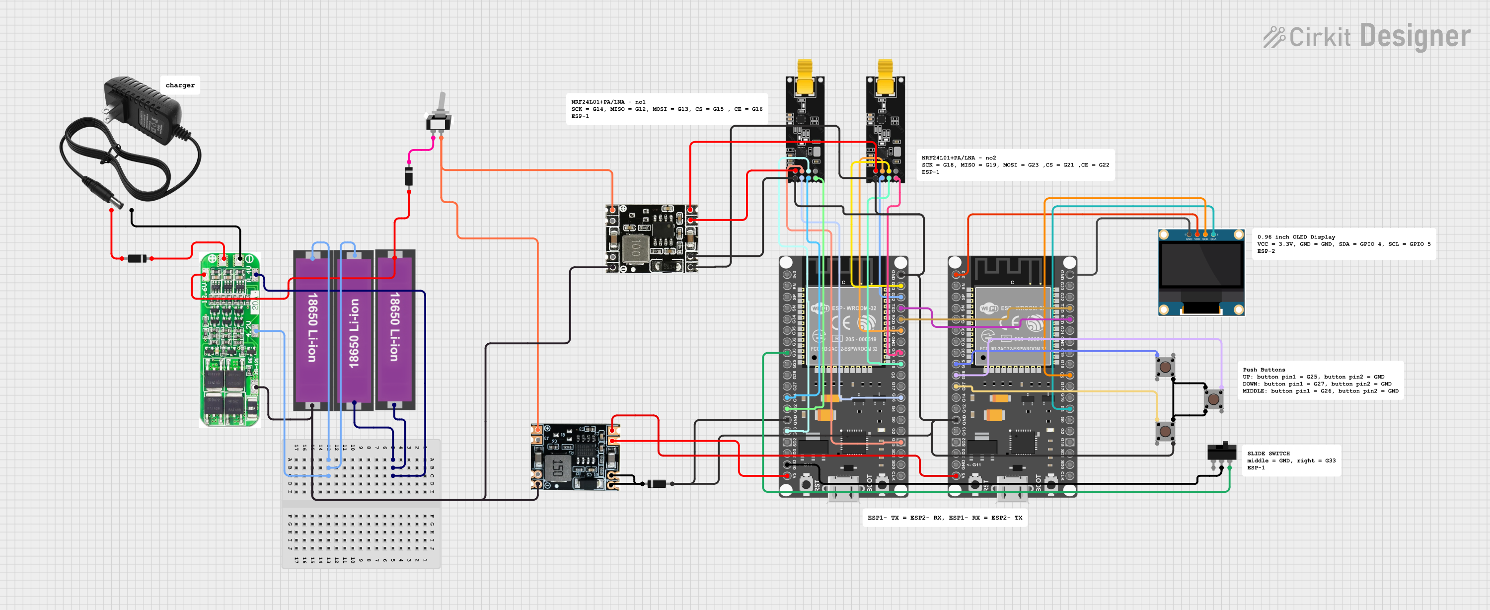
Wire both ESP32s per the circuit diagram. Connect OLED (SDA=4, SCL=5) and three buttons to ESP2. Connect NRF24 modules and slide switch to ESP1. Add 100µF caps to each NRF24 VCC/GND.
Connect ESP1 via USB. Open the flash page in Chrome or Edge. Click Install ESP1. Disconnect, connect ESP2, click Install ESP2. No Arduino IDE needed.
Cross-connect: ESP1 TX(17) → ESP2 RX(17) and ESP2 TX(32) → ESP1 RX(32). Connect a shared GND between both boards. This is mandatory.
Power both ESPs. The OLED shows the NUKRAX glitch animation for ~4 seconds then the main menu. JR.IO is at the top. Use UP/DOWN to navigate, MIDDLE to select.
Support @CosmoLanex
If this project was useful to you, consider supporting the development. Accepts multiple cryptocurrencies — no account needed.
Donate via Cryptoor ★ star the repository on GitHub